Decoding of CODA Data and Creation of ROOT Output
Decoding of CODA Data
CODA data from TIR/VME readout is stored in a home-grown binary data format, created at JLab, known as EVIO format.
All of the data files from various runs of data acquisition system are stored in /home/coda/coda/data, and are named test_XXXX.evio.0, where XXXX is the run number.
The first step in the analysis pipeline is to decode this data to extract the ADC and TDC values from each event in the run. These ADC and TDC values are stored in a ROOT data tree (ROOT is a C++ analysis framework developed for analysis of particle physics experiments at CERN - http://root.cern.ch/)
In Hall A/C at JLab, we have developed a ROOT-based analysis framework which includes components for decoding CODA data. The script for analyzing coda data from the Luter 345 setup is:
/home/coda/analyzer/decodeLuter18.C
One can decode the data from a particular run by doing the following:
$ hcana
hcana[0]: .x decodeLuter18.C(XXXX)
where again XXXX is the run number.
Analyzer/ Reading Data Words
Luter 345 VME Setup
The image shown is how the data taken from this setup will appear. The data words in the image are organized in an order as follows: a run count word that tells the run number of the file, a header word of the ADC to tell how many data words follow(this will always be 16 words), the data words of the ADC, a header word for the TDC (0-4 words in cosmic setup), the TDC data words, and a closing word that tells the analyzer to stop parsing(daebd00d).
- For more information about decoding the output buffers, read the user manual pages:
Hex to Binary Conversion
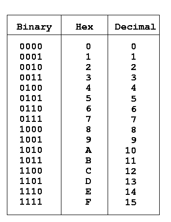
These words are shown in hexadecimal (the 0x denotes a hex number), so first they are broken down into 32bit binary words. First off, a word is just a number for the computer, which means this will just be converting a number from one base to another. Hexadecimal numbers have sixteen different digits, which range from 0 to F. Binary numbers only have two digits, which are 0 and 1. Because sixteen is a power of two (specifically 2^4), so a hex number can be written as a four digit binary number. The chart shows the conversion from hex to binary and decimal.
Example
Here is an example of how to break a hex word down to bits. The given hex word is:
0xfa8004081
The ‘0x’ just denotes that it is a hex word, so we ignore it for conversion. Following the chart, f becomes 1111, 8 becomes 1000, 0 becomes 0000, etc… When you put them all together our final binary word becomes:
11111000000000000100000010000001
The word make-up
The run count word simply recalls the run number of the data. This is used for labeling purposes.
ADC Header Word

TDC Header Word

Starting from the left, the first five bits are the geographical location. We should always expect 11111 for this part because our location is constant. The next three bits denote the kind of word. A header word will read 010 and a data word will read 000. For the header word, the next eight bits denote the crate being used. Both the TDC and ADC are operating out of crate zero, so those should be expected to be all 0’s as well. These are followed by 2 constant zero bits. And finally there are five bits that tell how many data words follow the header word. The rest of the bits have no meaning (should always be 0’s).
ADC Data Word

TDC Data Word

For a data word, the geo bits are the same. The three bits should read 000 to mean it is a data word. There will be three unimportant bits (again 0’s), followed by five channel bits. There will be one unimportant bit, and then the ADC will have a second unimportant bit, but the TDC will have a bit to determine valid data. If that valid bit is a 1 then the data is good. For both machines, there will be bits to determine whether the data is underthreshold or in overflow in that order. For our purposes, these bits should always be 0’s meaning that it is not underthreshold nor is it in overflow condition. The last 12 bits is the data itself.
The closing word is simply a constant telling the analyzer to stop parsing when it reads this word.
Example
Here is the word from the previous sections, to break it down in these meanings:
11111 000 000 0000 001 00 000010000001
The first five bits are 11111, as expected. The next three are 000, meaning it is a data word. Three unimportant bits. It is coming from channel zero. Three unimportant bits. Not it underthreshold nor overflow. And then the last twelve bits are the data.
Given the number of bits, it is usual (and useful) to express these words in hexadecimal format, or in the case of this example word:
0xF80084081
