Laboratory Preparation: Difference between revisions
en>Jlabdaq |
m 1 revision imported |
(No difference)
| |
Latest revision as of 17:59, 24 December 2024
Hardware Connection[edit | edit source]
Make sure the CPU module is on the far left side of the VME crate, followed by the trigger supervisor, then the rest of the modules.
Connecting High Voltage[edit | edit source]
1. Preparing High Voltage
To remotely access and control the high voltage supply, open the terminal and become super user by typing "su" , followed by the super user password. Once a super user, type "minicom" in the terminal. The serial connection to the HV supply should already be set as the default device, so once minicom is open the terminal should display the controls for the HV. Otherwise, the voltage can be adjusted directly from the power supply by using the knob controller.
Hint: If the display for the high voltage controller does not appear within minicom type caen to show the voltage control.
Hint: If a connection cannot be made the correct USB output needs to be chosen: minicom usb1
2. Attaching Cables
On the end of each PMT there is a connector labeled (HV) for high voltage. Here, securely fastened (HV) cables can be connected to the PMTs and linked with the power supply in separate channels. (Channels 0 to 3)
3. Polarity
Make sure that the polarity on the power supply is set to negative. If it is not, the polarity can be adjusted by removing the power supply, taking off its rear panel, and switching the polarity. (Refer to the power supply manual for further instruction)
Wiring Signal[edit | edit source]
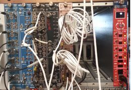
All four PMTs are connected with signal cable to a Linear Fan-in Fan-out module. From there the input signal can be copied and have up to four output signal destinations. The outputs from all four PMT signals are then connected to a Constant Fractional Discriminator (CFD) with a 2nm signal cable. Signals 1 and 2 from the CFD then pass through a Quad four-fold logic unit set to a coincidence level of 2. Signals 3 and 4 are also then ran through the Quad four-fold logic unit, and the outputs from both are also anded in the Quad four-fold logic unit. This final output is then wired to an oscilloscope or and ADC unit for analysis.
Gain Matching and Setting CFD Threshold[edit | edit source]
High Voltage Setup (From The Cart)[edit | edit source]
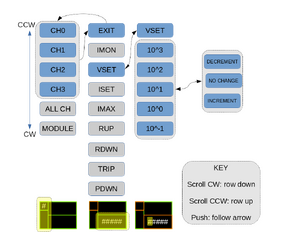
1. check/set high voltage from the power supply
The Powersupply we use is the CAEN N1470. This is a 4 channel power supply that lets us control very high voltages (very cool). Unfortunately, you need to go through a very convoluted menu to change anything this power supply does (not very cool). It is our intention in writing this section to reduce the headache this menu causes as much as possible.
When you have successfully located and identified the power supply, hopefully, the first thing you notice is the small rectangular screen located in the top quarter of the chassis. Notice also that there is a knob right below the screen (it glows blue when on). You will use this knob to navigate or change anything in the menu. The knob has three actions: Scroll CW, Scroll CCW, and Push. Any time you perform one of these actions, something on the screen will change.
Scroll CW until the number for the channel you want is in the top left corner. Push the knob, the top right box will turn orange. Scroll until the bottom right box says VSET. Push the Knob, the bottom right box sill also turn orange. Scroll until the digit you want to change is highlighted blue. Push the knob. Scroll CW to increment the number and CCW to decrement the number. Push the knob when you want to exit. Scroll until VSET is highlighted blue. Push the knob again, bottom right turns green. Scroll until you see EXIT. Push knob. Now everything is green and you are free to select another Channel.
Max Signal Size[edit | edit source]
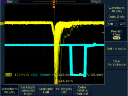
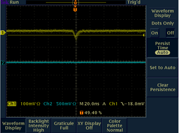
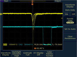
Change the persistence on the oscilloscope to infinity and and let it run for about 40 seconds. Choose ad dense patch of signals and this is now your max signal value.
Dark Current[edit | edit source]
Adjust the trigger on the oscilloscope so that it constantly triggers. The line should get onsidersbly darker because it is constantly resetting the screen.
Setting Threshold[edit | edit source]

1. Determining Threshold
Adjust the trigger on the oscilloscope until it is a few mV above the Dark Current.
You want it to be high enough that it is not constantly triggering on the dark current but still low enough that it catches all real events.
Take note of this trigger voltage and proceed to the next step.
2. Setting Threshold
For this part, a Voltmeter and a screwdriver must be used. Insert the positive probe of the voltmeter into the hole to the left of the T (in the image the whole colored in red). Ground the other probe on the screw (colored green or any other grounded part). Lastly insert the screwdriver into the hole to the right of T (colored orange). You should get a reading off the voltmeter that changes as you turn the screwdriver. Turn the screwdriver until the voltmeter reads off the trigger current you noted before.
Note: the voltages you read will be off by a factor of 10 so divide you readings by 10 to get the right number.
The holes labeled z are the DC offset voltage, for our purposes they can left untouched.