Scintillator Preparation: Difference between revisions
en>Jlabdaq No edit summary |
m 1 revision imported |
(No difference)
| |
Latest revision as of 17:59, 24 December 2024
Scintillator with Photomultiplier[edit | edit source]
A scintillator is a material that will experience luminescence when excited by ionizing radiation. When the material is struck by cosmic rays (particles) it re-emits the absorbed energy in the form of light.
Materials[edit | edit source]
1. Scintillator Paddle - Particle detection
2. Electrical Tape - Light Sealing/Strong Holds
3. Scissors - Cutting-Scrapping
4. UV Bonding Glue - Link Scintillator Paddles
5. Black Wrapping Material - Light Sealing
6. UV-A Lights - Cure the Glue
7. Photomultiplier Tube - Light Detection
8. Clamps - Hold Scintillators in Place
9. Ring Stand - Position UV Lights
10. Oscilloscope - Voltage/Signal Measurement
Gluing/Curing Process[edit | edit source]
In order to fix the broken scintillator set-up, a special UV glue can be utilized to bond the two pieces together.
Possible Steps[edit | edit source]
1. Remove previous bonding material by using scissors or a razor to scrape off the cement
2. Prepare a level surface for the two pieces set
3. Once level, glue one edge of the scintillator and firmly press it against the other
4. Clamp the ends to ensure a good connection
5. Use a heavy object to apply pressure at either end of the scintillators
6. Now apply the UV light (try to get as close as possible and cover a large amount of surface area)
7. Cure for the recommended amount of time for the bonding cement to harden
8. Let the glue dry and harden for a 24 hour period
Light Tight[edit | edit source]
To ensure that no light from the surroundings enters the scintillator or PMT during the experiment, the entire scintillator paddle must be wrapped in black electrical tape. It is important that all edges and seems of the scintillator wrappings were covered and light-proof.
Strength Test[edit | edit source]
Once the scinitillator is glued and taped, the repair is strength tested to make sure it can withstand further handling. The scintillator is picked up by the ends and flexed slightly to ensure a solid connection was made. Although the scintillator feels slightly fragile at the connection points, the repair seems to maintain enough strength.
Light Test[edit | edit source]
Once the scintillator is repaired, it can be tested for light leaks. The PMT is connected to a high voltage (HV) supply and signal cable. The signal cable is ran directly to an oscilloscope to measure the voltage spikes produced. Once attached, the HV is slowly raised until regular pulses are seen on the oscilloscope. When the HV was raised to about 12kV the oscilloscope picked up a constant signal, indicating a potential light leak. Unable to find the leak in the scintallator, it was found that there was an issue with the HV supply, and there were no leaks after all.
PMT Adjustments[edit | edit source]
Gain Matching[edit | edit source]
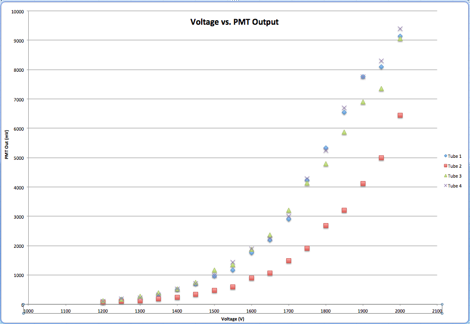
In order to gain match the scintillator setup, tests had to be run on each photo multiplier tube. By starting the high voltage at 1200 volts and increasing in 50 volt increments until reaching 2000 volts, the maximum voltage required to get at least one pulse was found at each interval. At each interval, the maximum voltage varied and was found using a series of steps. The first step was to see the pulses and determine where the majority of the peaks were hitting. Then, by using the trigger (which was the line that a pulse had to cross in order to show up on the screen), the area where the maximum voltage was kept could be found. After moving the trigger level down, the pulses would occur less frequently until finally reaching the point where a pulse would happen about once every second. This point was recorded as the maximum voltage. This test was done for each of the intervals on each of the four photo multiplier tubes. The graph below shows each of the four tubes and the voltage (on the x-axis) versus the maximum voltage to get at least one pulse (on the y-axis).

As expected, the maximum voltage to get at least one pulse increases as the voltage level increases. Three of the four tubes gave relatively close maximum voltages throughout each interval, but one of the tubes displayed maximum voltages significantly less than the other three.